Source Code |
|
Due to a number of requests, the source code for this project is now available on SourceForge.net |
This project has been ongoing for a year now. In brief it has been my attempt to convert my parents library of legacy super-8 mm film to DVD. I have actually got this working and have scanned several 400 foot rolls of film. If you want to learn how I did this and/or see some of the results, then read on.
Note: In what follows you can click on the images to enlarge
Like many people my age, my family has a legacy of old eight millimeter and super-8mm film footage that was taken when I was a kid. I looked into having this footage converted to DVD as a Christmas present for my parents and found that it would cost upwards of $1000 to have done by a reputable professional (there are many charlatans out there in this business currently). Instead I began to look into doing it myself. Having explored the various possibilities I found that I wasn't satisfied with the quality of what most Do-It-Yourself jobs would produce. Most of these techniques use a “Telecine” device to allow the video recording of a movie while it's being projected. I began to think about the possibility of scanning the film directly with a flatbed/film scanner. There is very little out there on the web where people have described how to do this and modern “film scanners” are typically limited in the formats that they support. Also, no one seemed to want to undertake the effort required to write the image processing software that would be required to do this automatically. The closest I had been able to find on the web was what “ SmartSoftware Italia” was doing.
Since I was looking for an interesting weekend project, and since I have a background that was languishing from lack of use in signal and image processing that included some computer vision, I figured I'd give it a try. This site documents the fruits (or lemons as the case may be) of this effort. I tried to make this site at multiple levels. Those who know almost nothing at all of image processing should be able to follow the higher level descriptions. Those interested in the particular techniques can dig down into the details.
I broke the project into two major pieces. The first is the process by which the physical media itself could be captured with a scanner and the second was computer image processing of the captured strips to created a movie. I thought that each of these pieces were somewhat, if not completely, automatable (which is a deviation from the above referenced site) and that, with perhaps a little help from friends more familiar with electronics and mechanics, I could (for considerably less than the $1000 the professional converters wanted) create a system that would allow me to implement these two phases with better results than any other do-it-yourselfer has been able to achieve. The consensus among many on the web is that, to preserve all of the information in the original format, 500 lines per frame would need to be achieved (and based on my experimentation, this seems to be a lower bound). This sets a lower bound on the quality of scanner I would need and gives me an idea of the magnitude of the image processing. Initially I calculated that, if I could scan a 50' roll of film in an overnight batch job, I would have achieved my goal and it seemed that both scan times and the image processing could be done within this time frame.
The entire project cost under $300 and only about 14 months of time. As far as programming the Software, Java provides the backbone to all of the Software written, but there is alot in C and C++ interfacing with the Java. The image processing is handled by JAI which is the image handling extentions to Java.
Early on I had various problems with scanning the film. I have recently settled on a solution that seems to be working adequately. If you are attempting this same project then it may help you to read some of the problems I ran across when I first started this project. You can find an older writeup in the section "Early Experiences with Film Capture."
It used to be difficult to find a scanner that could handle "transparent" sources. Most flatbed scanners are designed for scanning documents and photos, both of which are "reflective." Fortunately there has been a number of flatbed scanners coming
|
| The Specification (used by permission) |
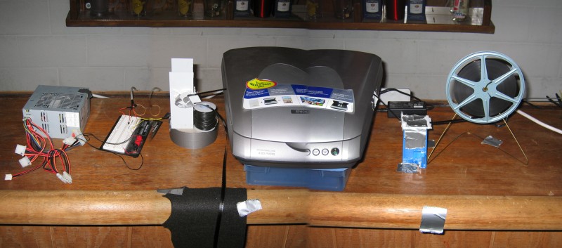
Since I had no intention of scanning all of that film by hand, I built a mechanical film-advancer controlled by the computer. The computer scans a portion of the film (usually about 14 frames at a time), forwards the film, and then scans again ("rinse, repeat") until the film is completely scanned. My original goal was to be able to scan a 50 foot roll of film overnight. I can do it in about 10 hours. I owe a HUGE thanks to Todd Campbell who published enough details for his own film forwarder that I could copy it. It took three attempts to get it right but I now have a mechanism capable of forwarding the film.
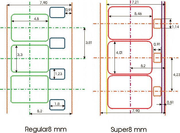
From multiple places on the web I found that a 500 lines per frame was required to preserve the original information in the film. Given the 500 lines per frame requirement, and the specifications (also here) of the film, 3000 dpi is a minimum. The Epson 4180 is a 4800 dpi (optical) scanner. It's about $200 and does a good enough job at 3200 dpi for a decent movie to be produced (and probably better than any professional Telecine outfit will do). I have run it at 4800 and produced movies but the raw scans just take up a lot more space and I'm not sure I'm getting any real benefit from it. If anyone has any reason why they think I should be scanning at the higher resolution, please let me know the reasons.
 |
| The setup |
Since I do not have much by the way of mechanical ability,
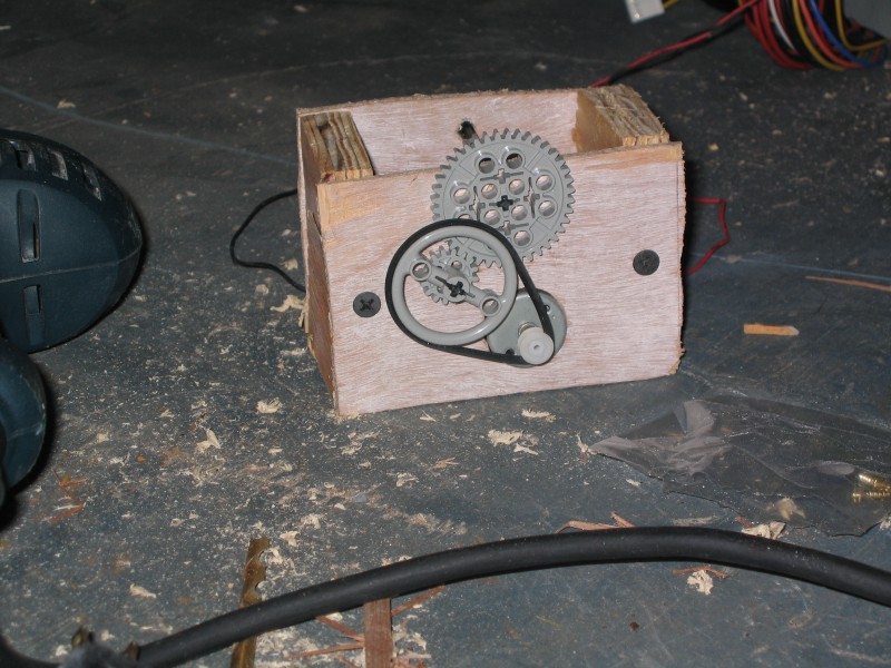 |
| Second attempt at a film forwarder |
 |
| Working Forwarder |
Because my electronics skill are at least as bad as my mechanical skills I decided that I would use the parallel port rather than the serial port that Todd Campbell used. The parallel port is much easier to control (typically) and doesn't require a controller circuit at the far end of the cable. From software you can easily set a data line high or low.
There are many great sites that document the details of the parallel port and how to interface to it. I bought a parallel port cable and cut off the printer port end and attached the wires to a breadboard. Currently I only use a single data line (D0) to turn on and off the motor. The motor is geared down so low that I didn't need the feedback that Todd Campbell's version used. Because my Image Processing software (see the section on Image Processing) expects some amount of overlap between successive scans and is robust enough to figure out how much overlap was included, I simply time the motor's "on" period instead of utilize feedback to count how far the film has moved.
In the next version of the forwarder I will certainly add the feedback. Not because I need to count the exact amount of film advancing (as explained, timing the motor works fine) but because the computer has no idea when there is a problem and even if the forwarder falls apart the computer will merrily advance the film. The feedback will allow me to shut down the forwarder and scanner if the film gets hung up.
Originally I used a simple transistor driver to switch a relay on and off which in turn sent power to the DC motor. At some point in my experimenting I burned out the relay and, not wanting to head out to the store to find another one, I hooked the transistor output directly up to the motor instead. To my surprise this worked fine and (so far) has not burned out my parallel port or the transistor. I would highly recommend buying a cheap PCI parallel port card for you computer rather than burn out the printer port on your motherboard - which is certainly a highly possible scenario. Adding limiting diodes to protect the parallel port and including the relay once will be in the next version.
|
import parport.ParallelPort; |
Currently, the computer language that I am most proficient in is Java. Therefore I stuck with it when I could, and the software that controlled the motor through the parallel port was no exception. Sun provides a "commapi," which is a Java interface to the parallel port. Unfortunately, it is difficult to get working and is overly complicated. I found, quite by accident, a much better java interface to the parallel port called ParPort by Juan Gabriel Del Cid. This is an incredibly simple and completely intuitive parallel port interface from java. A three line program using ParPort can turn the motor on and off. To the right is a trivial example. Passing "0" or "1" on the command turns the motor off and on (since the I'm using is D0).
TWAIN is a programming specification for interfacing to Image sources (like Scanners). The standard is published and maintained by The TWAIN Working Group. Before buying the Epson 4180 I made sure it was "TWAIN compliant" assuming that was all I needed to be able to write my own software to control the scanner. What I didn't know at the time was what a loose term "TWAIN compliant" really is. When I first started this project I thought that learning the TWAIN interface would be one of the easier tasks. In fact, it was much more difficult than I imagined. Not only because the specification itself is loaded with options, but because the spec is extensible and customizable by individual vendors; an attribute Epson took advantage of. Also, TWAIN is uniquely a Windows (or Apple - since they were developed by the same developers - Apple should have won that lawsuit) specification and requires manipulation of the Windows (Apple) event loop itself. Java is designed to be platform independent and access to the event loop is non-trivial.
Fortunately there is a library available (and a free version without fewer features) designed so developers can rapidly code to access TWAIN compliant devices (which means they shouldn't need to concern themselves with the handling of events in the event loop - it's handled by the library). It's called EZTWAIN by dosadi. This software not only provides a great API to access Image sources, the source code provided an invaluable framework for understanding TWAIN itself.
Two major problem still remained. One was the fact that Epson used custom extensions to TWAIN in their own software to communicate with the scanner. The other was that, in early experimenting with EZTWAIN, the scanner settings would all be lost between successive scans. During the first scan all of the settings could be entered and the scan executed. Then my software would repeat the scan but subsequent scans would have all of the settings returned to their default values. After the first scan I kept getting nice pictures of the inside of my scanner lid in all of the subsequent scans.
To solve both of these problems I wrote a TWAIN command interceptor. One good thing about the TWAIN specification is that it defines only two points of entry for all TWAIN applications. That is, all TWAIN messages from any software to any Image source all pass through only two functions in the TWAIN DLL. Therefore, I wrote my own TWAIN library that provided these methods and installed it on my system. My version of the TWAIN DLL logs all of the information that passes to these calls before passing them on to the original library, and then logs the responses and passes them back to the caller. This "TWAIN logger" or "TWAIN message interceptor" allowed me to monitor what Epson's software (the software provided with the scanner) was doing and allowed me to infer what even Epson's custom extensions to TWAIN were for. It also allowed me to see what my software needed to do to re-send all of the appropriate settings on each scan.
If anyone would like my TWAIN logger, just write me. As it is the Software that runs the scanner is a mix of Java, my own C++, and a hacked version of the free EZTWAIN, all geared specifically for my Epson scanner and not likely to run without modification against others. The TWAIN logger, however, should work with any TWAIN application.
The Image Processing can be divided into three main steps:
Step 1) From each scanned strip of film the computer needs to automatically locate and extract all of the frames and only the frames (“nothing but the frames Ma'am”) without missing any.
Step 2) The strips of film are scanned with a frame or two of overlap due to the fact that I did not want to require precise control over the motor (whether or not my hand constituted that motor). The software needs to be able to automatically find common frames from successively scanned strips no matter how much overlap there was (of course, I'm willing to concede the fact that I need, at least, one complete frame that is common to every two successive strips).
Step 3) The software needs to be able to collect all of the sequenced frames into a movie.
Additional requirements the software should accomplish include:
The ability to scan the film in any orientation (top-to-bottom, bottom-to-top, right-to-left, or left-to-right) and to automatically correct the film if it was scanned backward (so that the mirror image appeared in the scan).
A reasonable amount of distortion, misalignment, and resolution variation needs to be able to be tolerated so that if the strip was scanned with a slight angle (up to 10 degrees or so) or even if the angle varied over the length of the scanned strip, or the actual resolution of the scan varied slightly from what the scanner was allegedly set to, the software should continue to operate without a problem.
Processing should happen at least as fast as the Images could be acquired.
Before embarking on this section you should understand what an image is, how it is digitally represented, what pixels are (or a pixel is), how a pixel's bands contribute to the color, etc. There are many great sites out there that explain this at a simple level. If you are not familiar with these concepts then take a look at the 'Novice' section of the Links page for appropriate introductory materials.
This step, as I anticipated, was the most difficult of the image processing steps. The most prominent features, and those with a constant geometric relationship to each frame, are the sprocket holes in the film. As can be seen in the following diagram, once the center and exact orientation of each sprocket hole is known, then the frame itself can be extracted from the image. Additionally the edges of the film itself are very prominent features and serve (as it turns out) as necessary aids in correctly orienting the frame.
There are some rather well known computer vision techniques for detecting features in an image, and the sprocket holes and film edges are extremely prominent features. The process of identifying the sprocket holes can be broken into the following steps:
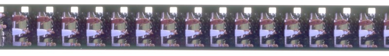
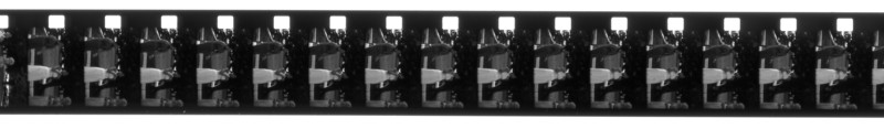
The starting point is the scanned image of a section of the film. In the examples that follow the resolution of the scan was 3200 dpi but, for the purposes of this presentation the images have been reduced and converted to compressed JPEGs. Here is a starting sample:
|
|
Remove the color from the image. - Most computer vision techniques that I am familiar with use the intensity levels of the pixels in the image to do their work. In the case when these techniques are extended into color images they simply operate on each band independently. In this case we want an quick and computationally efficient algorithm and when techniques are applied to all three color channels the amount of processing required is tripled. Extracting only the pixel intensities removes (arguably) 2/3 of the unnecessary (for our purposes) information. The result is a grayscale (or “black-and-white”) image:
 |
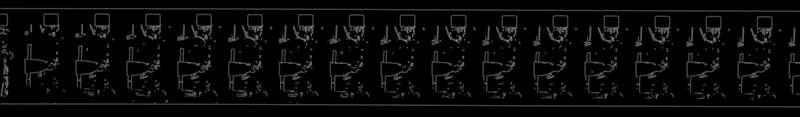
Edge Detection – There are various edge detection techniques in the computer vision literature but certainly one of the best for feature detection is the “Canny Edge Detection.” This web site will not document the details and theory behind this algorithm (even in the detailed section) because there are so many good descriptions out on the web already. Please see the links section if you are interested. The edge detection results in a monotone image. This image has only two values 'white' or 'black.' The 'white' occurs where the algorithm determines an 'edge' exists in the original image:
 |
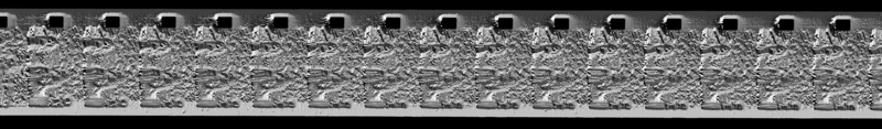
An edge detection is accomplished by measuring the image's “gradient.” The gradient of the image is a measure of how fast an image is changing as you progress across it in a particular direction. If you imagine the image as a terrain where the brighter the intensity at a pixel, the higher the point on the terrain, the gradient would be the direction opposite to the way a ball would roll if you placed it at that pixel. The “steeper” the slope this imaginary ball is rolling on, the higher the value of the gradient at that point. With this analogy in mind you can see that the gradient has a direction value at each pixel that corresponds to the orientation of the steepest change. This direction always points from darker area's to lighter areas of the image. The following image is a translation of this gradient direction into an intensity value at each pixel. The darkest region corresponds to a gradient direction of zero degrees (parallel with the X axis, that is, from right to left) and the brightest region corresponds to 360 degrees (or nearly so, since 360 degrees is the same as zero).
 |
Finding the edges of the film – As you can see from the edge detected image the sprocket holes and the edges of the film are the most prominent features. Currently the edges of the film are found in a rather simplistic shortcut method. This will change in the future since it currently requires that no (or very little) noise occurs outside of the edges of the film. Knowing the orientation of the film the software simply finds the first and last pixels in a given row (or column if the image is oriented vertically) and makes these pixels potential film-edge candidates. Then a simple statistical linear regression is applied to the film-edge candidates to find the best line that passes through all of the candidates, then outliers are removed. The regression and removing of outliers is done until the best line stops changing or the maximum distance from a potential film-edge pixel to the line drops below a certain threshold (which is currently a function of the length of the edge). Anyway, this technique is susceptible to noise outside of the bounds of the film-edges in the image and will probably be replaced with a “Hough Transform” (discussed next) in a future version.
Hough Transform – A Hough Transform is a rather ingenious means of matching edge pixels to features in an image. The technical details of a Hough Transform are documented in many places on the web (see the links section). In this case I modified the concept of what is called a “Generalized Hough Transform” for the specific purpose of finding sprocket holes. At a superficial level the hough transform can be thought of as a brute force search through the image for the best match to a parameterized model of the feature. It takes each edge pixel in the image and figures out every possible orientation (parameter) of the feature being searched for that could possibly result in that particular edge pixels. The gradient direction is used to aid in limiting the possibilities. The simplest feature (and the one the Hough Transform was initially developed with) is a line and to get a good overview of the general idea, take a look at: http://www.cogs.susx.ac.uk/users/davidy/teachvision/vision4.html. The hough transform can be computationally expensive so the search is bounded to the area of the image where the holes should be. In the previous step we found the film-edges in the image. Based on the orientation and whether or not the image is mirrored (both details must be supplied to the software) the software knows along which edge the sprocket holes should be. It uses this information to bound the search to a limited rectangular section of the image thus reducing computation complexity and the possibility of false detections due to “sprocket-hole-like” shapes in the actual frames themselves. The detailed section will assume the reader is familiar with the concepts and will detail the modifications that were made to the Generalized Hough Transform specifically for finding the sprocket holes. Technically minded individuals unfamiliar with the concepts that would like to follow the detailed discussion should consult the links section on the Hough Transform first.
Sprocket Hole Model Regression – The Hough Transform gives us an approximation for the features we are looking for. It results in groups of pixel locations where each group is considered a sprocket hole in the image. The next step is a simple regression to minimize the error between these pixel locations and the parameters of the model for the feature. The parameters of the model of the sprocket hole that are allowed to vary are the location of the center, the scale, and the rotation. Given a value for each of these an 'error' is calculated by measuring the distance between each edge pixel and the place where the model predicts that edge pixel should be given the center location, scale and rotation. The sum of the square of this error is then minimized numerically. The end result will be the best values for the center location, scale, and orientation (rotation) for the sprocket hole.
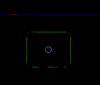
The result shown below is the end result of this process (it is actually the sprocket hole for the rightmost frame in the above sample at actual resolution). The film-edge pixels are in blue. The red pixels along the film-edge are those that were discarded during the regression process in step 4. The blue circle at the center of the sprocket hole is the center location found by the hough transform of step 5 and the yellow circle is the actual location after the regression of step 6 (remember the hough transform only results in approximate locations for the center of the sprocket holes). The green pixels are those that the algorithm considered part of the sprocket hole and the red ones were discarded during the final regression of step 6 due to the statistics (actually, the sprocket hole model I constructed assumes the corners are quarter-circles, they are usually dropped due to the fact that they really are not. Refining the model to more accurately reflect the actual hole (perhaps with a spline of some sort) should improve the detection – however, it currently seems adequate).
 |
Geometric interpretation – To find the exact frame a line is calculated from the center of the sprocket hole to the far edge which is perpendicular to the far edge. This line is the x-axis of the frame and should go through the center of the frame itself (for super8 format, For 8mm it will define the boarder between frames). The software currently scales the image so that the sprocket hole center and the far edge of the film are always in the same place and orientation (a “nearest neighbor” interpolation is utilized currently – since the scale should be close to 1) with respect to the final frame.
Now that each of the strips for a roll of film has been converted into frames we need to automate the means of finding which frames overlap. A precise amount of overlap is not required, as long as there is at least one whole frame that is common to every two successive strips. In the example that follows there are four frames of overlap (in most of my suite of sample data there is only one, but this one serves as a good example).
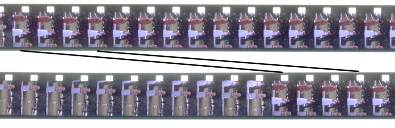 |
This is done in a rather straightforward manner by doing a cross-correlation between the frames of the two strips. A correlation is the measure of “sameness” between two signals and the normalized correlation coefficient will vary from -1 to 1. In the case where it is closer to -1 the signals (or images in this case) are said to be “inversely correlated” and indicates that there is a strong tendency that where one image has high values, the other has low, and vs. vrs. Where the correlation coefficient is close to one, the images are said to be “highly (directly) correlated” and indicates that in areas where one image has higher values, the other does also. There are several sites referenced in the link section that explains statistical correlation and how to interpret it.
In looking at the correlation then of the second to last frame in the first strip against all of the frames of the second strip we see that the maximum occurs where one would expect it; against the third frame of the second strip. The best matches between every frame in the first strip against every frame in the second is as follows:
First strip, frame 11 matches second strip, frame 1 (0.9860801584887924)
First strip, frame 12 matches second strip, frame 2 (0.9830295454817305)
First strip, frame 13 matches second strip, frame 3 (0.9856143948566214)
First strip, frame 14 matches second strip, frame 4 (0.9906575623572221)
Notice the matches: 14 -> 4, 13->3, 12->2, and 11->1. These all indicate the same thing, that there is a four frame overlap between the strips. Also note, these four correlation coefficients are the highest 4 among the entire set. From this the sequence of frames follows directly.
There are probably many ways to do this. I opted to build an Motion-JPEG (MJPEG) AVI file from the frames. My Correlation software optionally outputs all of the sequenced frames into an MJPEG AVI file and as long as an MJPEG codec is available on the system, this AVI file can be played and subsequently converted to an DVD compliant MPEG2.
To create the AVI file from my own software I hacked a publicly available MJPEG AVI file maker called JPEG to MJPEG AVI converter (or " jpegtoavi") to make it callable from Java and allow it to handle adding JPEG files one at a time rather than having them all up front (by default, "e;jpegtoavi" needs a list of all of the available files up front). For anyone interested, the Java interface has the following methods:
|
class MJPEGWriter |
To use it you simply call the initializeMJPEG once. Then call appendJPEGFile for each JPEG file you want to add to the AVI file (in the correct sequence of course), and then close the file providing the desired frames per second playback. Anyone that would like a copy of the source code can simply email me and I'll send it to you. It's implemented in Java and C++ so you'll need a C++ compiler also (Don't worry, everything I write works with Borland's free C/C++ compiler on Windows). It is COMPLETELY undocumented and provided without warranty.
For playback, you will need an MJPEG codec installed on your system. There are a number of them out there but the PicVideo MJPEG codec by Pegasus Imaging Corporation is so much better than anything else I've found out there I decided to purchase a copy. There are some free ones available which also work but they require a really fast CPU and spending a lot of CPU on decoding makes a later conversion to MPEG2 (required to write to a DVD) problematic.
Another option is AVISynth and the ImageSequence plugin. This will allow you to play the raw frames without compiling them into an AVI file AS IF they were in an AVI file. The advantage of this approach is that the frames do not need to be in JPEG format. However, this pegs my CPU and causes problems with the conversion to MPEG2 for DVD writing.
Another option is FFMPEG. This is a media capture/convert/format/etc catch all program. It can be used to go straight from files to an MPEG2 file. However, I found it difficult to adapt to my needs (the source code was rather complex), it's very inconsistent (on more than one occasion I needed to downgrade the version to get rid of inexplicable problems), and the quality of the result leaves much to be desired (admittedly, this last one may be more user issues than software issues).
Once the movie is in a playable AVI form there are a number of MPEG2 encoders available. You could go the free route with the aforementioned FFMPEG but that suffers from the problems already mentioned. The best reference for these tools on the web is VideoHelp.com (formerly DVDRHelp.com and VCDHelp.com). Make sure you check the tools section. The tool I've been using is TMPGEnc Plus.
Here is a clip from a movie I recently put together. It's my sister and I as kids. This is a DivX avi file and will require an MPEG4/DivX codec. You can get the DivX codec from their site. Or optionally you can click on the frame below and load the plugin (if you don't already have it). In this case you will have the movie embedded in your browser (a much nicer way to view it).
A number of people have asked me for the source code. I hope anyone that is really that interested will be willing to contribute their own work back to the project. You can find the source on SourceForge.net
If you finally decide it's just all too much, the guys at MovieStuff have a line of do-it-yourself film to video products that have produced better results than what I've been able to achieve.